Optimized Wireframe Rendering: Part I
💡 This post is part of a three-part series on optimized wireframe rendering. You can navigate the series here:
- Part I: Introduction and Initial Challenges
- Part II: In Search of Equal-sized Edges
- Part III: A Deep Dive into NVIDIA Whitepaper & Fixing its Shortcomings
This is my first actual blog post! I had planned to write other blog posts first, but I decided to write about a recent subject I worked on instead. So, wireframe rendering it is!
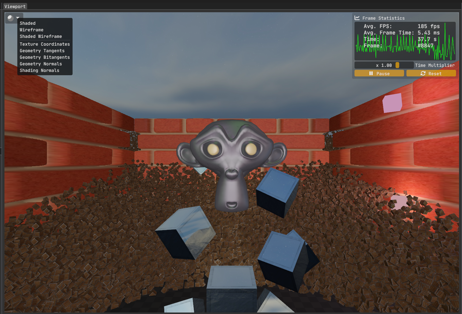
Anyway, the reason I got into this topic in the first place is because I wanted to add “Editor Shading Modes” as I call it, similar to Unity’s, to my study renderer Kakadu. I’ve so far implemented the following modes:
- Shaded (i.e., regular rendering path, what the standalone build would use),
- Wireframe,
- Shaded Wireframe
- Texture Coordinates,
- Geometry Tangents,
- Geometry Bitangents,
- Geometry Normals,
- Debug Vectors (TBN as vectors instead of colors)
Next, I plan to implement the shading normals mode.
On this blog post, we’ll be focusing on the wireframe and the shaded wireframe rendering though.
Motivation
A natural question to ask is why I’m writing a blog post about something as simple as wireframe rendering? In OpenGL you just call glPolygonMode( GL_FRONT_AND_BACK, GL_LINE ) and you are done right? Well, not quite.
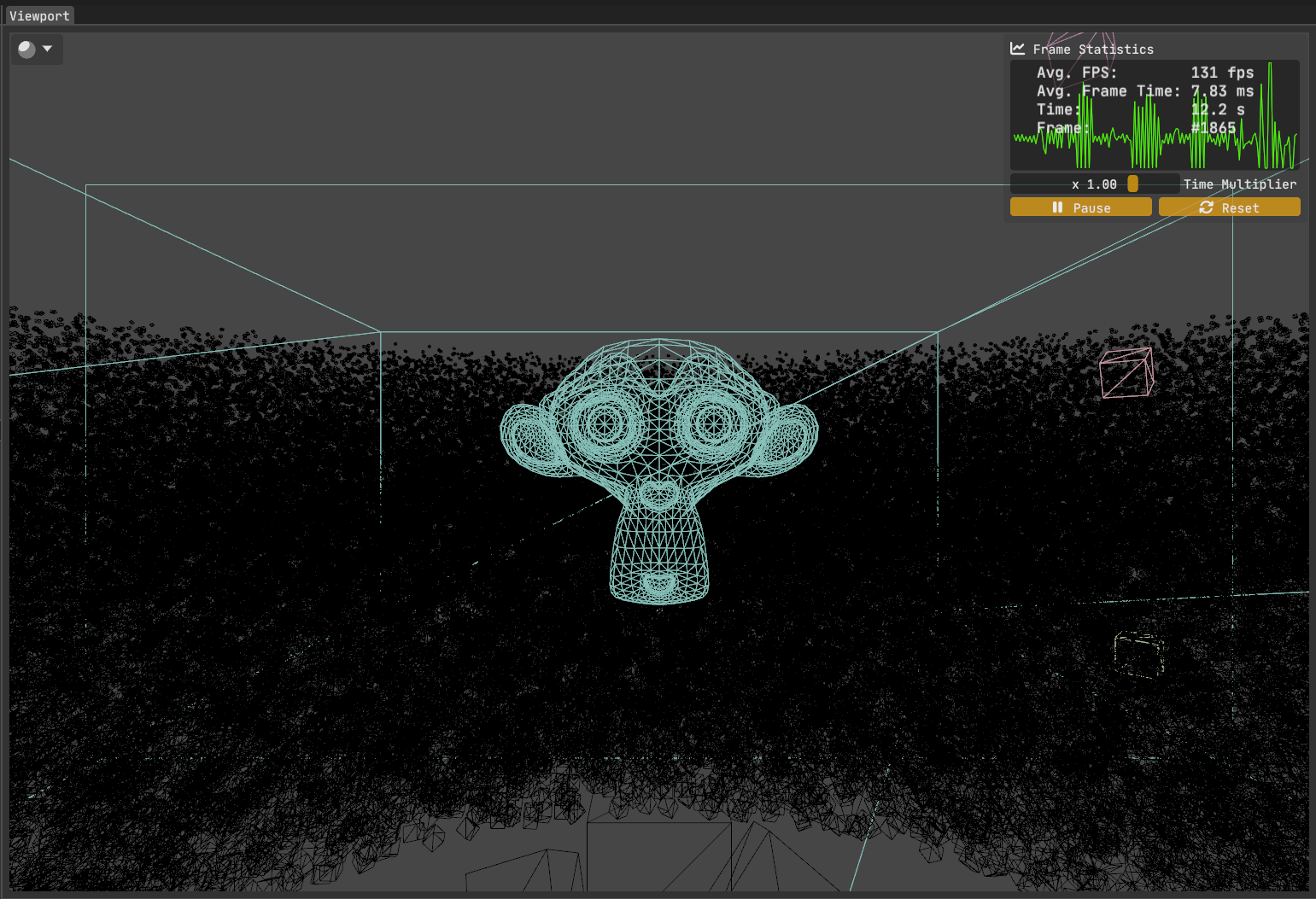
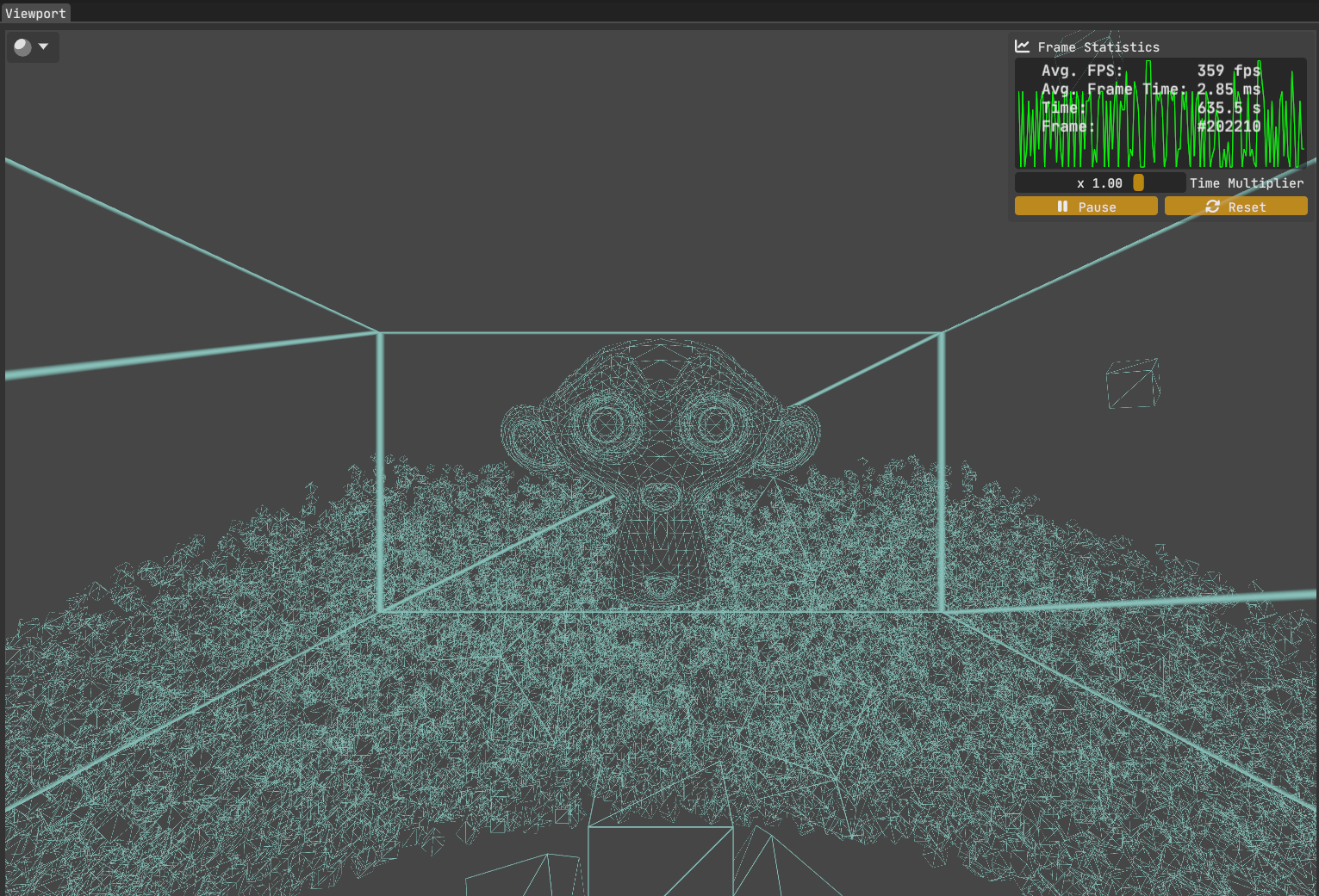
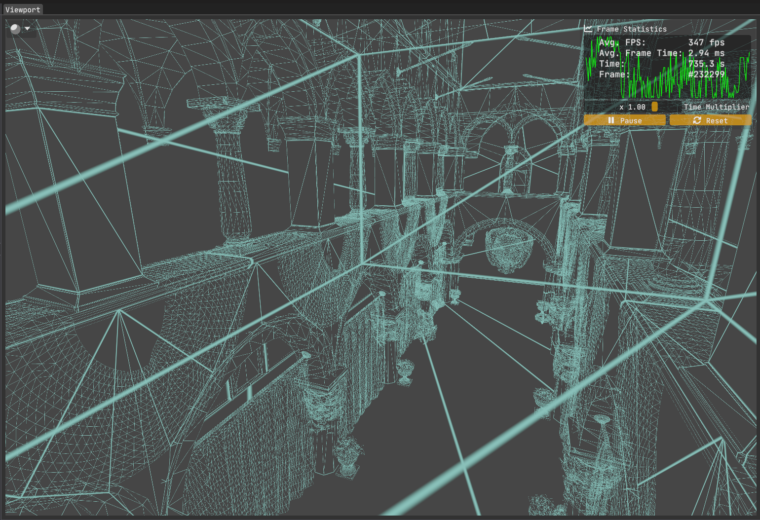
Compare the avg. FPS values in figures 1 & 2. There is a %30 performance drop!
I would expect wireframe mode to be much faster since I’m using a much simpler shader without any lighting, texturing, parallax mapping, etc. So what gives?
Searching on the web, I quickly found out that mainstream GPUs are specialized to work with triangles primarily, which in turn makes them less efficient when dealing with other primitives such as lines. I suspect one of the strengths of AMD’s PRO lineup & the NVidia’s Quadro lineup of graphics cards are their superb line rendering capabilities, which is utilized a lot in CAD applications.
Upon discovering this, the first thought I had was “Then how about I send triangles down the line instead of lines and only shade the borders of those triangles?” I know I’m not the first graphics programmer to think of this as I can recall at least 10 applications that are rendering wireframes efficiently off the top of my head. Still, I thought I had come up with a nice idea and a fun little challenge that I could quickly get up and running.
Attempt 1: Using Barycentric Coordinates To Find Triangle Edges
To attack this problem, the initial idea I had was to utilize barycentric coordinates. Since they encode the normalized distance from the edges, comparing the minimum of this triplet against a user-defined threshold value means we can now detect the borders in a triangle. Sweet!
How do we get the barycentric coordinates of a triangle? The fragment shader, where we do… fragment shading, does not have access to this by default. While the rasterizer certainly has this information as it uses it to calculate interpolated position, depth & attribute values, as well as to handle backface culling & triangle classificiation etc., it is not exposed to the shaders, let alone the fragment shader which is where we will determine whether a fragment is inside the border or not.
It is clear that we need to manually calculate them. It can not be done easily inside the fragment shader because we need to access information on all 3 vertices simultaneously. That means we go to the vertex shader. We can take advantage of the fact that vertex shader gets access to a special predefined variable gl_VertexID. We can simply do this:
/* Wireframe.vert:
 * Inputs are omitted for brevity. */

out vec3 varying_bary_coords;

void main()
{
	varying_bary_coords = vec3( gl_VertexID == 0,
				 		 		gl_VertexID == 1,
				 		 		gl_VertexID == 2 );
}
This would yield the barycentric coordinates:
- Vertex 0 -> <1,0,0>
- Vertex 1 -> <0,1,0>
- Vertex 2 -> <0,0,1>
The rasterizer takes care of interpolating these values across the triangle, and now we have the interpolated barycentric coordinates ready for use inside the fragment shader.
What about the second triangle of the mesh? Assuming it has the vertex IDs 3, 4, 5, the code above will give us all zeroes for our coordinates. An easy fix is to take the modulo of the vertex ID:
varying_bary_coords = vec3( gl_VertexID % 3 == 0,
			 				gl_VertexID % 3 == 1,
			 				gl_VertexID % 3 == 2 );
Producing:
- Vertex 3 -> <1,0,0>
- Vertex 4 -> <0,1,0>
- Vertex 5 -> <0,0,1>
Assuming the 2nd triangle was indeed comprised of vertices 3, 4 & 5, this could work. However, what’ more likely is that at least one vertex is shared between the two triangles. Perhaps the vertex ordering is something like this:
0 1 2
0 2 3
What then? Sure, we can do some basic arithmetic to get it to work, probably. But this assumes the vertex ordering is known and follows a pattern.
It is easy to see that this approach of assigning bary. coords. to vertices based on the vertex ID will not hold up when we have a real model at hand, vertices of which will not follow any ordering, at least we will certainly not be able to verify it without traversing them on the application side first.
Another approach would be to calculate and send barycentric coordinates as vertex attributes. This would work but needs pre-processing of model data. This means adding two extra floats per vertex (the third coordinate can simply be calculated from the first two as they sum to 1) , which increases memory bandwidth (which may not be a big deal for a game engine’s editor though).
It becomes apparent that we need access to all three vertices simultaneously in order to perform this in the shader. At this point, you’ve probably guessed it: the geometry shader is the solution! Since it can access all vertices in a triangle, it is the perfect fit.
/* Wireframe.geom:
 * Transforming positions to clip space is left to the vertex shader. */

#version 460 core

layout ( triangles ) in;
layout ( triangle_strip, max_vertices = 3 ) out;

out vec3 varying_bary_coords;

void main()
{
    /* Vertex 1: */
    gl_Position = gl_in[ 0 ].gl_Position;

    varying_bary_coords = vec3( 1.0, 0.0, 0.0 );

    EmitVertex();

    /* Vertex 2: */
    gl_Position = gl_in[ 1 ].gl_Position;

    varying_bary_coords = vec3( 0.0, 1.0, 0.0 );

    EmitVertex();

    /* Vertex 3: */
    gl_Position = gl_in[ 2 ].gl_Position;

    varying_bary_coords = vec3( 0.0, 0.0, 1.0 );

    EmitVertex();

    EndPrimitive();
}
This geometry shader sets the barycentric coordinates per vertex and passes those onto the fragment shader, which are interpolated across the triangle.
Now that we have vertex ordering independent barycentric coordinates for every triangle in our mesh, we can shade the borders:
/* Wireframe.frag: */

#version 460 core

in vec3 varying_bary_coords;

out vec4 out_color;

uniform vec4 uniform_color;
uniform float uniform_line_thickness;

void main()
{
    float min_bary_coord = min( min( varying_bary_coords.x,
									 varying_bary_coords.y ),
							   		 varying_bary_coords.z );

    if( min_bary > uniform_threshold )
		discard;

	out_color = uniform_color;
}
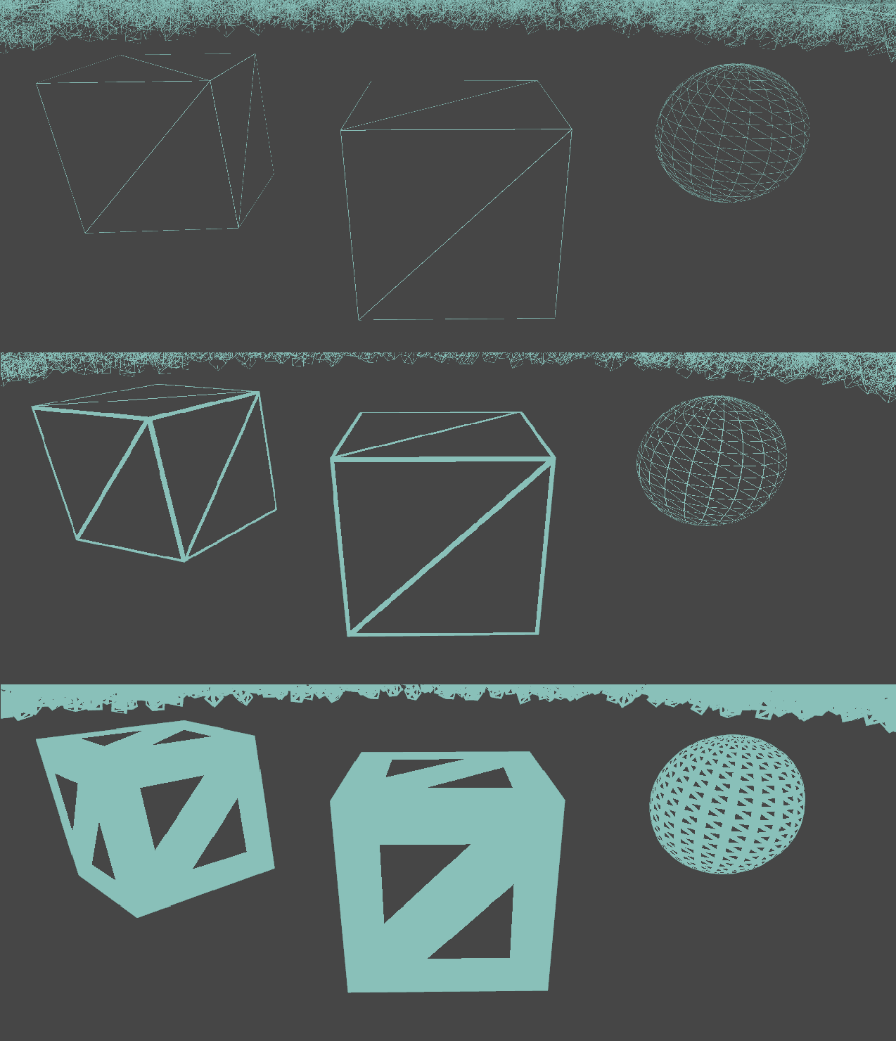
Before I show you the FPS values, I want to point out one important fact: We lost anti-aliasing inside the interior of the triangle. Let’s look at a close-up of the cube in the middle:
This was rendered with 4x MSAA on. So why does the interior look jagged while the exterior looks smooth? That’s because we introduced shader aliasing when we discarded pixels inside the fragment shader. This is a binary decision - pixels are either fully discarded or fully kept.
So, what can we do to resolve this? A natural idea that comes to mind is to make this a not-binary decision. We could leverage alpha blending and go for a smooth transition instead of a binary on/off behaviour.
Using Alpha Blending to Smooth Out The Transition
/* Wireframe.frag:
 * Input/output/uniform values are omitted. */

void main()
{
    float min_bary_coord = min( min( varying_bary_coords.x,
									 varying_bary_coords.y ),
							   		 varying_bary_coords.z );

    float edge_factor = 1.0 - smoothstep( 0.0, uniform_line_thickness,
										  min_bary_coord );

    out_color = vec4( uniform_color.rgb, edge_factor );
}
Enabling alpha blending and using smoothstep instead of discarding pixels based on a threshold ensures a smoother transition between the border and the interior of the triangle.
And here’s the final image of the initial scene, now rendered with our custom wireframe method:
Looking at the avg. fps, we now see the expected performance boost of the wireframe mode over the filled mode: A ~95% increase over the shaded version and a ~175% increase over the good old glPolygonMode( GL_FRONT_AND_BACK, GL_LINE ).
Bonus shot of Sponza:
What’s Next?
We achieved a nice wireframe solution without breaking the bank in terms of performance. It’s easy to conceptualize and implement. Although, we could do better with the inconsistent edge thickness, dependent on triangle size in screen-space. But that’s for the next blog post.