Optimized Wireframe Rendering: Part II
💡 This post is part of a three-part series on optimized wireframe rendering. You can navigate the series here:
- Part I: Introduction and Initial Challenges
- Part II: In Search of Equal-sized Edges
- Part III: A Deep Dive into NVIDIA Whitepaper & Fixing its Shortcomings
In the last post, we implemented a triangle-based wireframe solution using barycentric coordinates to shade the edges of each triangle. We also brought back anti-aliasing, which we previously got “for free” with the default glPolygonMode( GL_FRONT_AND_BACK, GL_LINE ) API - assuming anti-aliasing was enabled to begin with.
However, a glaring issue remained: line thickness is inconsistent, with some triangles showing thicker edges than others. In this post, we’ll attempt to fix that by slightly changing our approach.
Motivation
Ideally, we want the line thickness to be consistent across all edges. While we’re at it, it would also be nice to be able to specify line thickness in pixels (i.e., in screen-space units).
Let’s recall: In the context of wireframe rendering, a barycentric coordinate can be thought of as encoding a normalized perpendicular distance from the fragment to the edge opposite a given vertex. What if, instead of using the barycentric coordinates directly, we worked with these distances (per fragment) in the fragment shader? This way, we could specify a threshold value (in whatever unit these edge distances are in) and shade based on this comparison. This should, in theory, give us perfectly consistent line thickness across all edges.
The process of converting barycentric coordinates to edge-to-vertex distances involves calculating the actual distance from the vertex to its opposing edge, then multiplying this distance by the corresponding barycentric coordinate. This ensures the distance is interpolated across the triangle, and each fragment receives three distance values, one for each triangle edge.
What would the space and unit for these edge distances be? Obviously, it can not be the object space, as it is unique per object. If we take a look at the world and camera spaces, we can quickly realize that they are not ideal. These spaces do not account for perspective correction, which ensures the triangles closer to the viewing plane appear larger, and those further away appear smaller. For example, specifying an edge distance of 2 cm in world space wouldn’t be meaningful; A line of 2 cm closer to the camera is expected to appear thicker than a line with the same thickness but further from the camera.
Then it’s clear we should focus on the spaces further down the graphics pipeline. We have the clip space, the Normalized Device Coordinates space (NDC from now on) and the screen space. Clip space is out, as it is the space right before the perspective divide, and therefore does not account for the perspective. Of the remaining two, screen space is perhaps the more intuitive choice at first glance - simply because its units are the most human-friendly. We could set the line thickness as “2 pixels”, which is immediately more understandable than say, “2 units in NDC space”.
Attempt 2: Using Screen-Space Edge-to-Vertex Distances Instead of Barycentric Coordinates
I’ll present the code first, then explain what it does and why it works the way it does:
/* Wireframe.geom:
 * Transforming positions to clip space is left to the vertex shader. */

#version 460 core

#include "_Intrinsic_Other.glsl"
// Contains intrinsic uniforms such as the viewport size etc.

layout ( triangles ) in;
layout ( triangle_strip, max_vertices = 3 ) out;

out vec3 varying_edge_distances_in_pixels;

void main()
{
    /* Vertex 1: */
    gl_Position = gl_in[ 0 ].gl_Position;

    /* Swizzling is employed to copy the w into the z below: */
    vec3 vtx_to_edge_clip_space = ( gl_in[ 1 ].gl_Position.xyw +
                                    gl_in[ 2 ].gl_Position.xyw ) * 0.5
                                  - gl_in[ 0 ].gl_Position.xyw;
    vec2 vtx_to_edge_screen_space =
      /* Perspective division: */
      ( ( vtx_to_edge_clip_space.xy / vtx_to_edge_clip_space.z )
      /* Viewport transformation: */
        * 0.5 + 0.5 )                // [-1,+1] -> [0,1] + move origin.
      * _INTRINSIC_VIEWPORT_SIZE.xy; // [ 0,+1] -> [screen resolution].

    varying_edge_distances_in_pixels =
      vec3( length( vtx_to_edge_screen_space ), 0.0, 0.0 );
    // Above line essentially multiplies by the bary. coord. <1,0,0>.

    EmitVertex();

    /* Vertex 2: */
    gl_Position = gl_in[ 1 ].gl_Position;

    vtx_to_edge_clip_space = ( gl_in[ 0 ].gl_Position.xyw +
                               gl_in[ 2 ].gl_Position.xyw ) * 0.5
                             - gl_in[ 1 ].gl_Position.xyw;
    vtx_to_edge_screen_space =
      ( ( vtx_to_edge_clip_space.xy / vtx_to_edge_clip_space.z )
        * 0.5 + 0.5 )
      * _INTRINSIC_VIEWPORT_SIZE.xy;
    varying_edge_distances_in_pixels =
      vec3( 0.0, length( vtx_to_edge_screen_space ), 0.0 );

    EmitVertex();

    /* Vertex 3: */
    gl_Position = gl_in[ 2 ].gl_Position;

    vtx_to_edge_clip_space = ( gl_in[ 0 ].gl_Position.xyw +
                               gl_in[ 1 ].gl_Position.xyw ) * 0.5
                             - gl_in[ 2 ].gl_Position.xyw;
    vtx_to_edge_screen_space =
      ( ( vtx_to_edge_clip_space.xy / vtx_to_edge_clip_space.z )
        * 0.5 + 0.5 )
      * _INTRINSIC_VIEWPORT_SIZE.xy;
    varying_edge_distances_in_pixels =
      vec3( 0.0, 0.0, length( vtx_to_edge_screen_space ) );

    EmitVertex();

    EndPrimitive();
}
The transformation for the first vertex is annotated in the code. As the comments explain, after computing the vertex-to-edge vector in clip space, we proceed with the perspective division, which brings the coordinate into NDC. We then remap the range from [-1,+1] to [0,1] & shift the origin from the center to the bottom-left corner (for OpenGL. This should be top-left in Direct3D). Finally, we multiply by the screen resolution, converting our coordinates to screen space, where our units are now in pixels.
The fragment shader is straightforward. In fact, it’s semantically identical to the one from the previous post - the only difference is that the uniform has been renamed.
/* Wireframe.frag:
 * Input/output/uniform values are omitted for brevity. */

void main()
{
    float closest_edge_distance =
      min( min( varying_edge_distances_in_pixels.x,
                varying_edge_distances_in_pixels.y ),
                varying_edge_distances_in_pixels.z );

    float edge_factor = 1.0 - smoothstep( 0.0f, uniform_line_thickness,
                                          closest_edge_distance );

    out_color = vec4( uniform_color.rgb, edge_factor );
}
Let’s see how we performed:
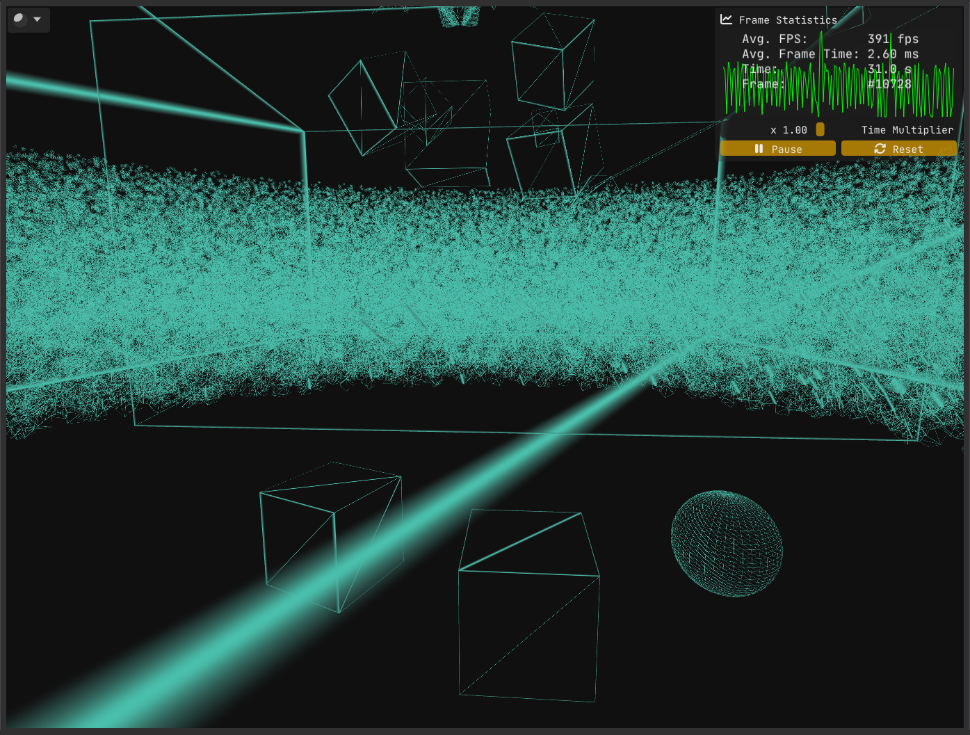
Despite our intention and effort to achieve consistent edge thickness, Figure 1 clearly shows that our implementation has a flaw. The question is, what went wrong?
As it turns out, there are multiple problems at play.
The first problem stems from where and how we compute the vertex-to-edge vector. We calculated this vector in clip space and only then converted it to screen space.
However, clip space is a 4D homogeneous space where the w component varies per vertex. Geometric operations such as calculating midpoints or distances are only meaningful if the points share the same w; otherwise, these operations yield incorrect results. Because vertices typically have differing w values, it’s safer and more correct to perform such calculations after perspective division, in screen space.
To highlight the issue, try inverting the order: first convert positions to screen space, then compute the vertex-to-edge vector. You’ll find the results differ numerically, which is a strong hint that the original method is flawed.
The fix for this issue is straightforward - and it’s exactly what I described earlier: convert positions to screen space first, then perform your geometric calculations there.
/* Wireframe.geom:
 * Transforming positions to clip space is left to the vertex shader. */

#version 460 core

#include "_Intrinsic_Other.glsl"

layout ( triangles ) in;
layout ( triangle_strip, max_vertices = 3 ) out;

out vec3 varying_edge_distances_in_pixels;

#define ClipSpaceToScreenSpace( p ) ( ( p.xy / p.w ) * 0.5 + 0.5 ) * _INTRINSIC_VIEWPORT_SIZE.xy

void main()
{
    vec2 vtx_0_screen_space = ClipSpaceToScreenSpace( gl_in[ 0 ].gl_Position );
    vec2 vtx_1_screen_space = ClipSpaceToScreenSpace( gl_in[ 1 ].gl_Position );
    vec2 vtx_2_screen_space = ClipSpaceToScreenSpace( gl_in[ 2 ].gl_Position );

    /* Vertex 1: */
    gl_Position = gl_in[ 0 ].gl_Position;

    varying_edge_distances_in_pixels = vec3( length( ( vtx_1_screen_space + vtx_2_screen_space ) * 0.5 - vtx_0_screen_space ), 0.0f, 0.0f );

    EmitVertex();

    /* Vertex 2: */
    gl_Position = gl_in[ 1 ].gl_Position;

    varying_edge_distances_in_pixels = vec3( 0.0f, length( ( vtx_0_screen_space + vtx_2_screen_space ) * 0.5 - vtx_1_screen_space ), 0.0f );

    EmitVertex();

    /* Vertex 3: */
    gl_Position = gl_in[ 2 ].gl_Position;

    varying_edge_distances_in_pixels = vec3( 0.0f, 0.0f, length( ( vtx_0_screen_space + vtx_1_screen_space ) * 0.5 - vtx_2_screen_space ) );

    EmitVertex();

    EndPrimitive();
}
With the first problem out of the way, let’s examine the current state:
While the first issue has been resolved, Figure 2 makes it clear that problems remain.
The second problem is trickier to uncover (not that homogeneous coordinates are anything to sneeze at!). Solving it requires a deeper understanding of rasterization. I went looking for a more detailed breakdown of the rasterization process than I had seen before - and I found this excellent write-up on the awesome Scratchapixel. Another good read on the subject is Fabian Giesen’s renowned series “A trip through the Graphics Pipeline 2011” - a must-read for any graphics programmer, in my humble opinion.
The issue at hand has to do with how the interpolants/varyings (as well as the depth value) are interpolated across the triangle. Regular linear interpolation doesn’t cut it, as the perspective distorts distances, leading to incorrect results (The Scratchapixel article provides an example that mathematically shows the discrepancy between linear interpolation and the correct approach, which is explained below).
The correct way to interpolate the varyings and the depth value is to use something called perspective correct interpolation (also termed hyperbolic interpolation or rational-linear interpolation), which involves
- multiplying by the reciprocal of the depth value (
1/w) to normalize the interpolant (essentially compensating for the perspective distortion, removing the non-linear effect of depth on the interpolant and bringing the value into a space suitable for linear interpolation), - linearly interpolating the value,
- multiplying by the depth value to reapply the perspective distortion.
The thing is, this is already being performed by the GPU, as it is the default interpolation method for varyings.
In our case, this results in the perspective distortion being accounted for twice. Think about it: when we convert our edge distances from clip space to screen space - via perspective division - we’re already factoring in the perspective distortion. Then, when the GPU performs perspective correct interpolation (which happens automatically), it interpolates the values in a way that compensates for the depth non-linearity, leading to an incorrect double accounting of perspective distortion.
The fix is straightforward: Qualify the interpolant varying_edge_distances_in_pixels with the noperspective keyword, which instructs the GPU to linearly interpolate the values instead of using perspective correct interpolation. The only place where we need to use this qualifier in modern OpenGL is inside the fragment shader, but it wouldn’t hurt to put it in the geometry stages as well. And pre OpenGL 4.3, it is actually mandatory for the qualifiers on the inputs and outputs to match.
Do we have a complete solution with all the kinks worked out now?
Unfortunately we have another problem and this time there is no easy way to get around it. Let’s start by analyzing the problem.
I’ll just state what the visuals tell us: When a triangle goes outside the view frustum (i.e., it is clipped), the whole triangle is shaded with the wireframe color. But there’s a subtlety: This does not happen when the triangle is clipped against the left, right, top and bottom frustum planes, as well as the far plane.
The problem only happens when a triangle is clipped against the near plane. Let’s take a look at two cases to better find out what’s going on.
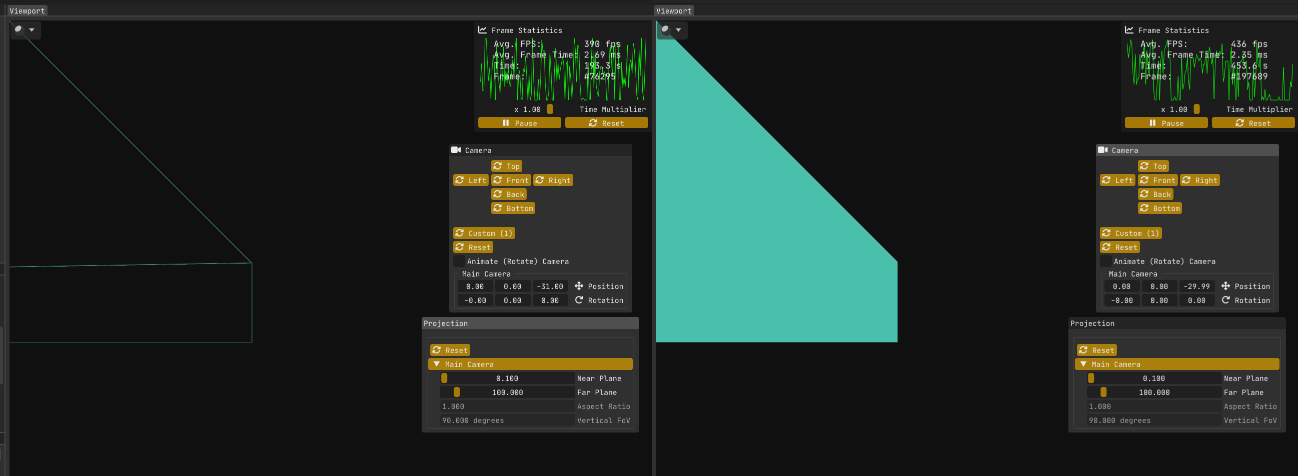
The first image (left) in Figure 4:
The wall/quad on the left is rotated on the vertical (Y) axis by 90 degrees, so it is perpendicular to the near plane.
The top left vertex is at world point <-15,+15,-30>.
The camera is positioned at world point <0,0,-31>.
My engine Kakadu is left handed with x y z pointing to the right, up and forward respectively.
The wireframe solution works without issue, because w >= 0 for all vertices.
The second image (right) in Figure 4 is showing the same scene, but now the camera is at z = -29.99.
The bug is present, because now the top left vertex has w = -0.01.
The second image (or rather me using abs( closest_edge_distance ) in the fragment shader to try to find out what the hell is going on) reveals something strange: the screen-space edge distances calculated in the geometry shader aren’t just incorrect - they’re negative, which makes no sense for a Euclidean length.
Why is that? Let’s look at some plots!
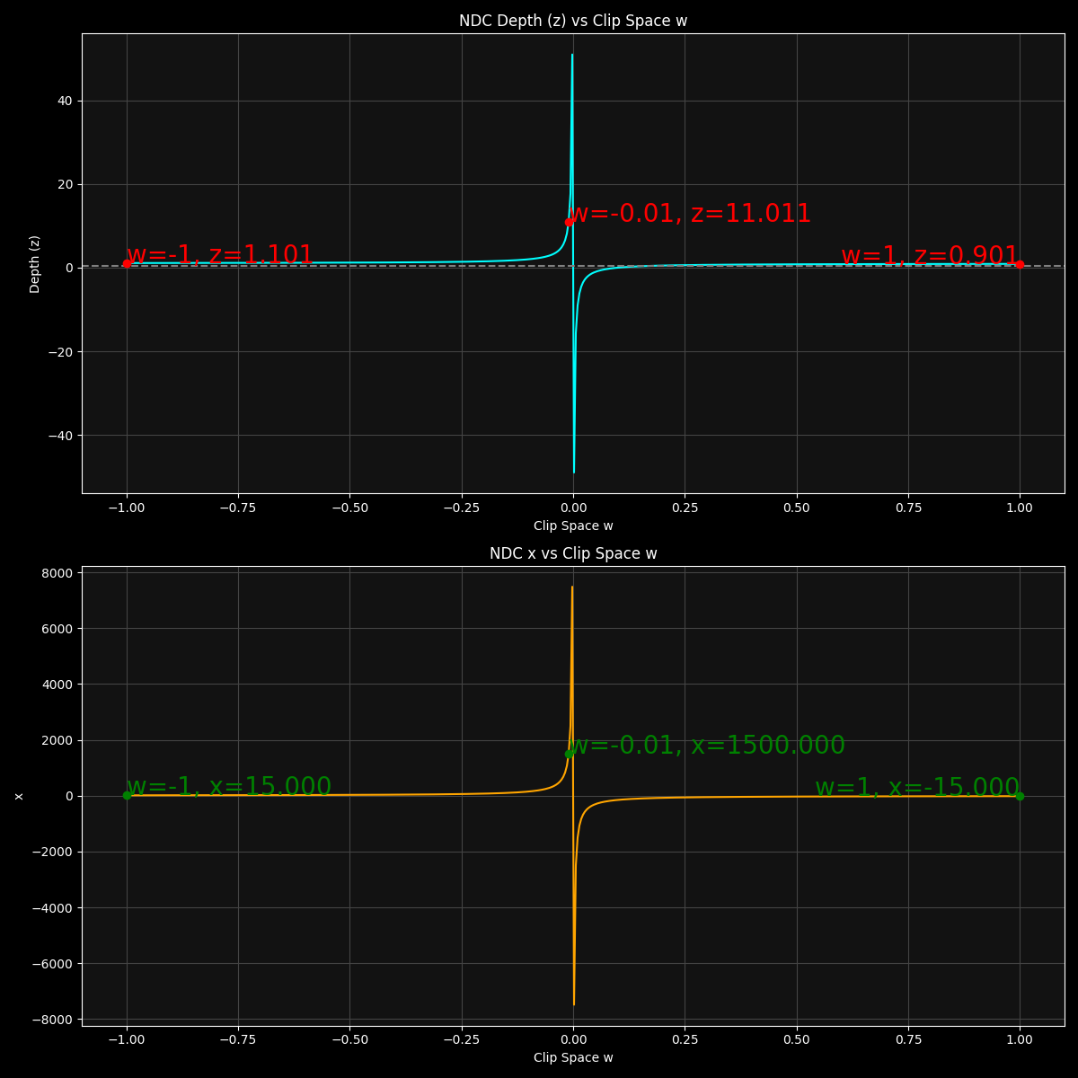
As the plots in Figure 5 show, the distortion effect is the strongest near w = 0, as the x and z values becomes more and more extreme as the w approaches 0. There is also a discontinuity at w = 0 as the x and z values become infinite.
For the second image in Figure 4, the top left vertex has w = -0.01, which maps to NDC x coordinate of x = +1500 (and similarly y = +1500 which is not plotted). These are absurdly large values considering the NDC space has the range [-1,+1] for all three axes. I knew that perspective distortion was a thing but after actually plotting these values, I have a newly found appreciation for how extreme it gets closer to w = 0.
At this point, I don’t have a definitive explanation for exactly why these negative values occur in this situation. While I have some strong clues - involving the roles of near-zero or negative w division, linear noperspective interpolation of these varyings, and subtle numerical precision issues with huge numbers - I may be off base in parts.
Honestly, pinning down a complete, airtight mathematical proof is tricky and beyond the scope here (and certainly beyond my reach as of writing this). If anyone reading this knows the precise cause or has insight, please comment below - I’d love to learn more as well!
To put things into perspective (pun not intended), for the second image in Figure 4 (the buggy version), these are the vertex-to-opposing-edge-midpoint distances:
In NDC:
Edge 1-2 midpoint: (1500,    -750,     21.022022)
Edge 2-3 midpoint: (749.875, 0.125,    11.511027)
Edge 1-3 midpoint: (749.875, -749.875, 11.511027)
In screen space:
Edge 1-2 midpoint: (1440960, -404580)
Edge 2-3 midpoint: (720900,  607.5)
Edge 1-3 midpoint: (720900,  -404572.5)
P.S.: There is a great paper titled “Shader-Based Wireframe Drawing” that implement the same idea. Unfortunately, I found it a bit late, as it would have saved me considerable time diagnosing some of the problems I encountered, such as the noperspective issue. But hey, that pushed me to dive deeper into rasterization so that’s not a bad thing!
Thankfully, it also led me to another insightful NVIDIA white paper, but I won’t spoil that here - I’ll save it for Part III.
In the next and final installment of this blog series, we’ll see if we can come up with a way to get around this new hurdle (spoiler alert: we will; by shifting the calculation of edge distances to the fragment shader, where the geometry has already been projected and clipped).
Stay tuned!