Optimized Wireframe Rendering: Part III
💡 This post is part of a three-part series on optimized wireframe rendering. You can navigate the series here:
- Part I: Introduction and Initial Challenges
- Part II: In Search of Equal-sized Edges
- Part III: A Deep Dive into NVIDIA Whitepaper & Fixing its Shortcomings
In the last post, we worked through an implementation aimed at equal-thickness lines in screen space but we fell short of reaching our goal as vertices behind the near plane caused our distance-to-edge calculations to go haywire, resulting in the entire triangle being rendered as an edge, i.e., the whole triangle is completely filled.
In this post we will examine what NVIDIA did back in 2007 in this whitepaper and implement it ourselves to see whether they found a foolproof solution for unprojectable (behind the near plane) vertices.
Spoiler alert: They did not.
A Walkthrough of NVIDIA’s Solid Wireframe White Paper
General Algorithm Outline
The paper first outlines the algorithm for the general case, where all three vertices of the triangle are in front of the near plane so projection does not pose any problems. The outline is:
- Transform the mesh vertices from model space into projection space as usual.
- Pass each fragment the triangle’s geometric data needed to calculate its distance to the edges in screen space.
- For every fragment, determine the minimum distance to the triangle’s edges in screen space.
- Render the fragment only if that distance is within the threshold that defines the line’s thickness.
They consider the shortest distances from the fragment to the triangle’s edges (i.e., perpendicular lines to the edges) by calculating the 3 heights of the triangle in screen space.
In contrast, we calculated the distances from each vertex to the midpoint of the opposing edge, which is another metric for deducing how close a fragment is to a given edge.
Both methods rely on the noperspective interpolation of these distances to determine the fragment’s position relative to the triangle.
The Issues
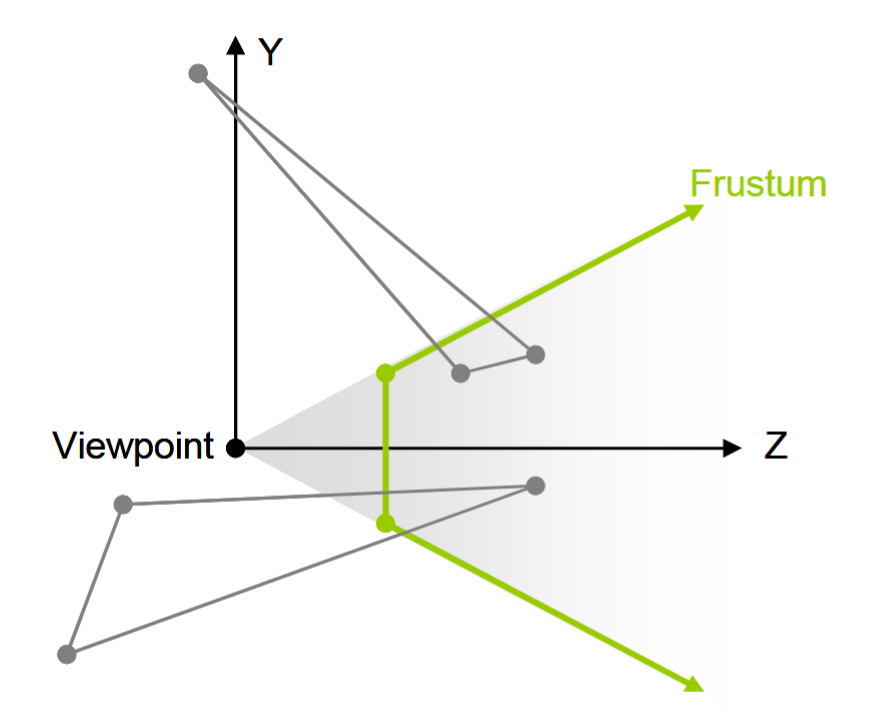
After elaborating on this general-case algorithm, the paper quickly notes the issue with the proposed approach: Those pesky behind the near plane vertices causing issues with projection, just like we saw in our own attempt. As mentioned in the paper, these vertices have $z <= 0$ in view space coordinates.
The paper glosses over what these issues actually cause in practice, and honestly if NVIDIA can get away with that I don’t feel too bad about leaving it open-ended back in Part II 🤷
The Tricky Cases
The paper proposes an alternative method for these tricky cases: Instead of computing the screen-space heights of the triangle in the geometry stage (problematic for unprojectable vertices), it computes the edge data for all 3 edges and relays it to the fragment shading stage. The fragment shader can then employ this data to decide whether a fragment is close to an edge or not.
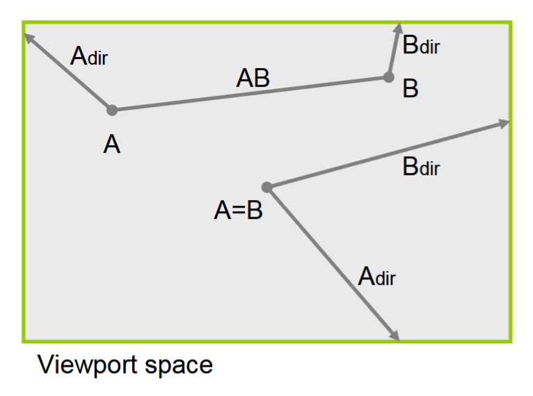
As the figure from the paper shows, there are either 2 visible and 1 unprojectable vertices or vice versa.
The algorithm cleverly computes in the geometry shader:
- The positions of $A$ & $B$ (these may be the same depending on the case).
- The directions $ \overrightarrow{A}_{dir} $ & $ \overrightarrow{B}_{dir} $, from $A$ & $B$ to the invisible vertex (or vertices).
The actual distances to edges are calculated in the fragment shader as mentioned.
The paper then explains how they map triangle projection cases based on vertex view space z coordinate, which determines what the data calculated in the geometry shader actually represents:
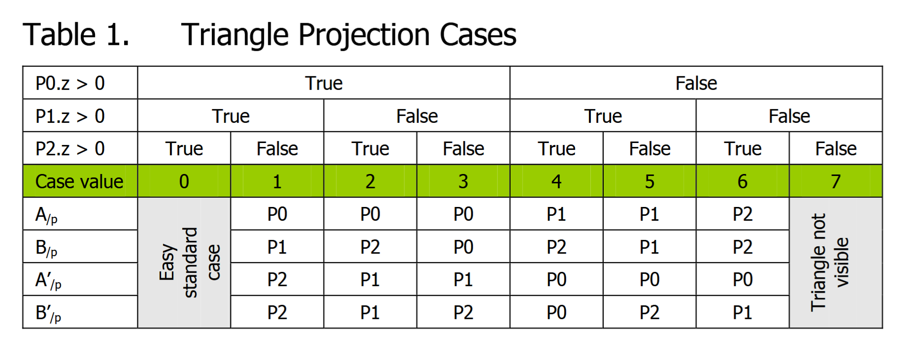
For case ID 2 for example, vertex 1 is not projectable and is invisible whereas vertices 0 and 2 are in view. So the positions of $A^{\prime}_{\text/p}\ \text{and}\ B^{\prime}_{\text/p}$ pointing to the same invisible vertex are calculated for this triangle.
In practice, they calculate the directions from the visible vertices (or vertex) to the invisible vertex (or vertices) and output this information to the fragment shader instead of calculating the position of the invisible vertex (which is unprojectable as we know).
At this point, you might be wondering how a direction vector from a properly projected vertex to another vertex lying behind the near plane (and yet still gets projected somewhat) can make any sense mathematically or geometrically.
Well I did, and in fact I struggled to internalize it for a while. But once I sketched it out, I realized something: While the position vector of a projected-but-unprojectable vertex can cause numerical instability (once rasterization & interpolation come into play, as we saw earlier) and is best avoided, the direction vector to/from such a vertex actually produces the expected direction/line! Take a look at this art piece I drew:
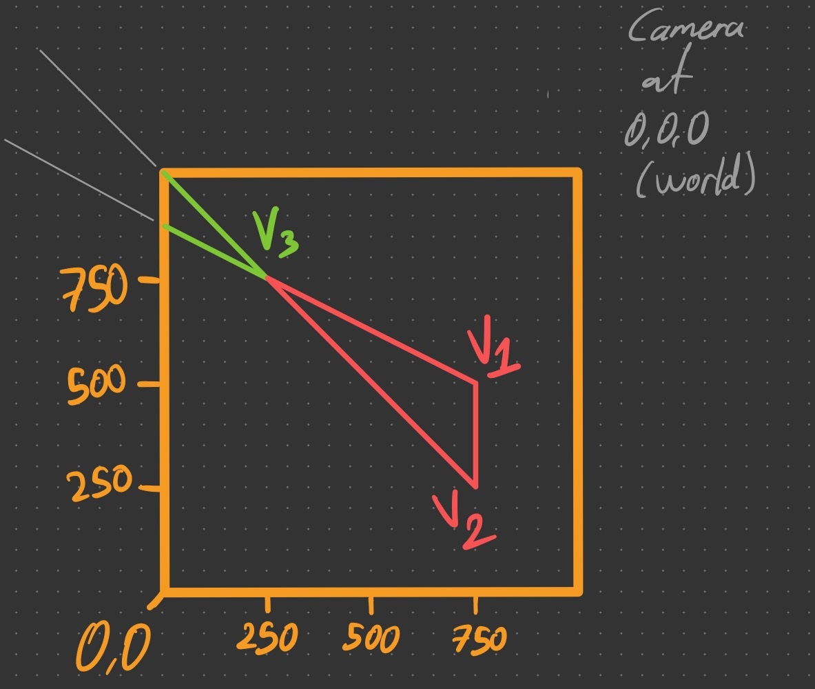
Let’s unpack what the drawing shows us: $V_{3}$ is an in-view vertex that can be projected just fine. $V_{1}$ and $V_{2}$ are originally (i.e., before projection) out of view and their positions can be deduced visually by tracing the green lines starting from $V_{3}$ followed by the grey thin lines outside the viewport.
The key observation is that projecting these vertices despite their unprojectability lands them in a position such that they are colinear with the clipped triangle edges they originally constitute! This is because division by a negative $w$ flips both $x$ & $y$ coordinates and scales them, effectively placing the projected point on the same original line.
In other words, while the projected $V_{1}$ does not make sense visually and may not be used in further calculations reliably due to numerical instability, the line from $V_{1}$ to $V_{3}$ (or vice versa) is still the same line we were looking for in the very first place.
And since we only care about the shortest distance from the fragment to an edge, the direction of the line is unimportant; if we have a mathematical definition of the edge/line, we can calculate the shortest distance to it without any problems.
Now that we know why this works, let’s focus on the rest of the paper, focusing on the implementation of the proposed technique.
Implementation Details
What’s neat about the whole edge case detection and edge info collection geometry phase (see Figure 3) is that it is constant across the triangle. This saves unnecessary calculations and also, as noted in the paper, results in coherent branching for all rasterized fragments of the triangle in question. Sweet!
Case ID 0 is the general case, which we know how to implement by now.
Case ID 7 is culled in the geometry phase as all vertices are behind the near plane.
Remaining 6 cases, from IDs 1 to 6 are implemented such that four vec2s (or two vec4s) are used for the four necessary 2D position/direction vectors needed, as we need one direction and one position to mathematically define a line and we need two lines at least. For cases 1, 2 & 4, we are interested in 3 edges actually, since the edge $AB$ is also in view (see Figure 2).
Here is the layout of the uniforms calculated in the geometry shader, in order:
- The 1st
vec2holds the projected position of $A$. - The 2nd
vec2holds the projected direction from $A$ to $ \overrightarrow{A}_{dir} $. - The 3rd
vec2holds the projected position of $B$. - The 4th
vec2holds the projected direction from $B$ to $ \overrightarrow{B}_{dir} $.
As mentioned, direction from $A$ to $B$ is also needed for some cases and it is easily derived in the fragment shading stage since the screen-space positions $A$ & $B$ are already calculated by now.
Or is it?
In Practice
At this stage I was overjoyed and convinced that everything made sense, so I went on and implemented the technique. After working out some kinks, I had a working implementation in Kakadu.
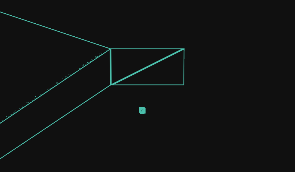
As seen in Figure 6, one edge of the upper left triangle of the leftmost wall has visual artifacts.
To better understand what’s going on, I implemented a quick magnifier overlay via ImGui, with 4x, 8x, 16x & 32x zoom levels.
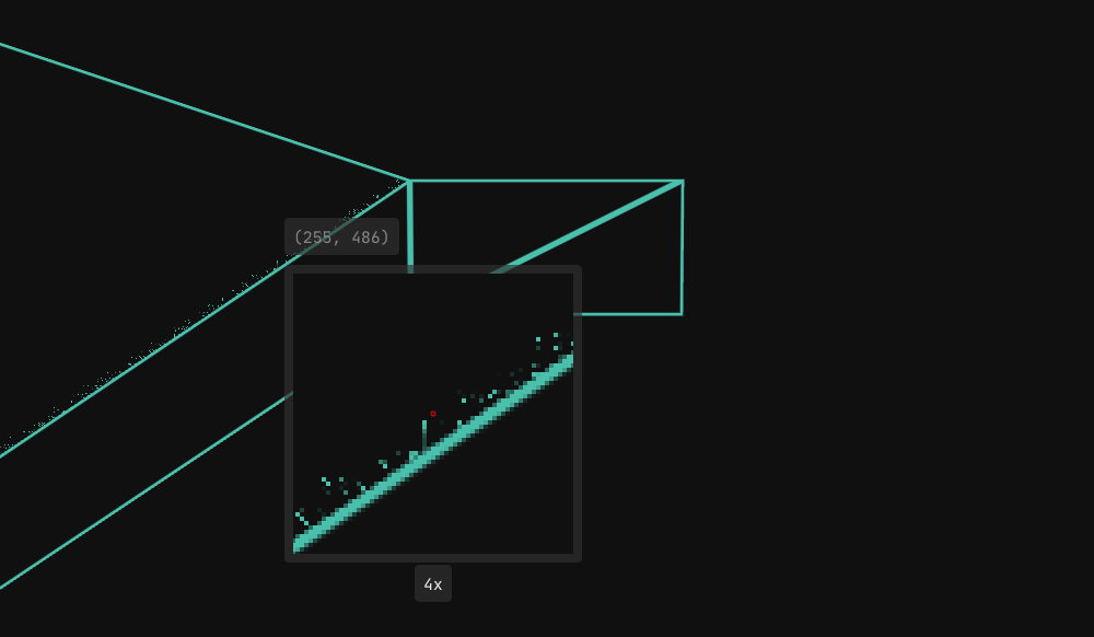
While it is neat, it didn’t directly help me build intuition about why the artifact occurs.
I compared my implementation with both the source and the binary of the demo accompanying the white paper, available for download from NVIDIA here.
The source matched my code and I even changed some of my own calculations to better match their formulas although it didn’t change anything as both formulas produced same results numerically.
The demo binary, on the other hand, showed no glitches or artifacts whatsoever. The paper’s implementation didn’t seem to suffer from the problem, despite the code being identical. Did the D3D10 driver behave differently? Maybe rasterization rules differ between D3D10 and OpenGL? What gives? (More on this later in the post.)
I then went on to create a little triangle debugger window for Kakadu, hard-coded to show what is going on for this leftmost wall quad’s top & bottom triangles.
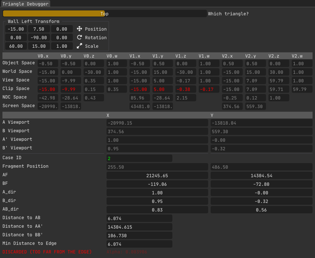
Back to the topic at hand. With the triangle debugger now showing unprojectable vertices in red, displaying the case ID for the triangle, as well as the screen-space coordinates of calculated edges, it was now obvious what was going on in Figure 6;
The glitchy edge corresponds to the edge $\overrightarrow{AB}$ for this triangle/case ID combination.
If we take a look at $A$’s screen-space (or viewport) coordinates, we see that it is a whopping $-20990.15, -13818.04$.
Those are certainly absurd coordinates sure, but we know that we can have a stable direction calculated from $A$ to $B$ nevertheless. And indeed the $\overrightarrow{AB}_{dir}$ vector shown in the triangle debugger is 100% correct as I have verified it by comparing the end points’ coordinates.
As you know we also need a position on the line to be able to define the line mathematically, and that is exactly where the problem lies.
Let’s sketch this triangle and take a closer look.
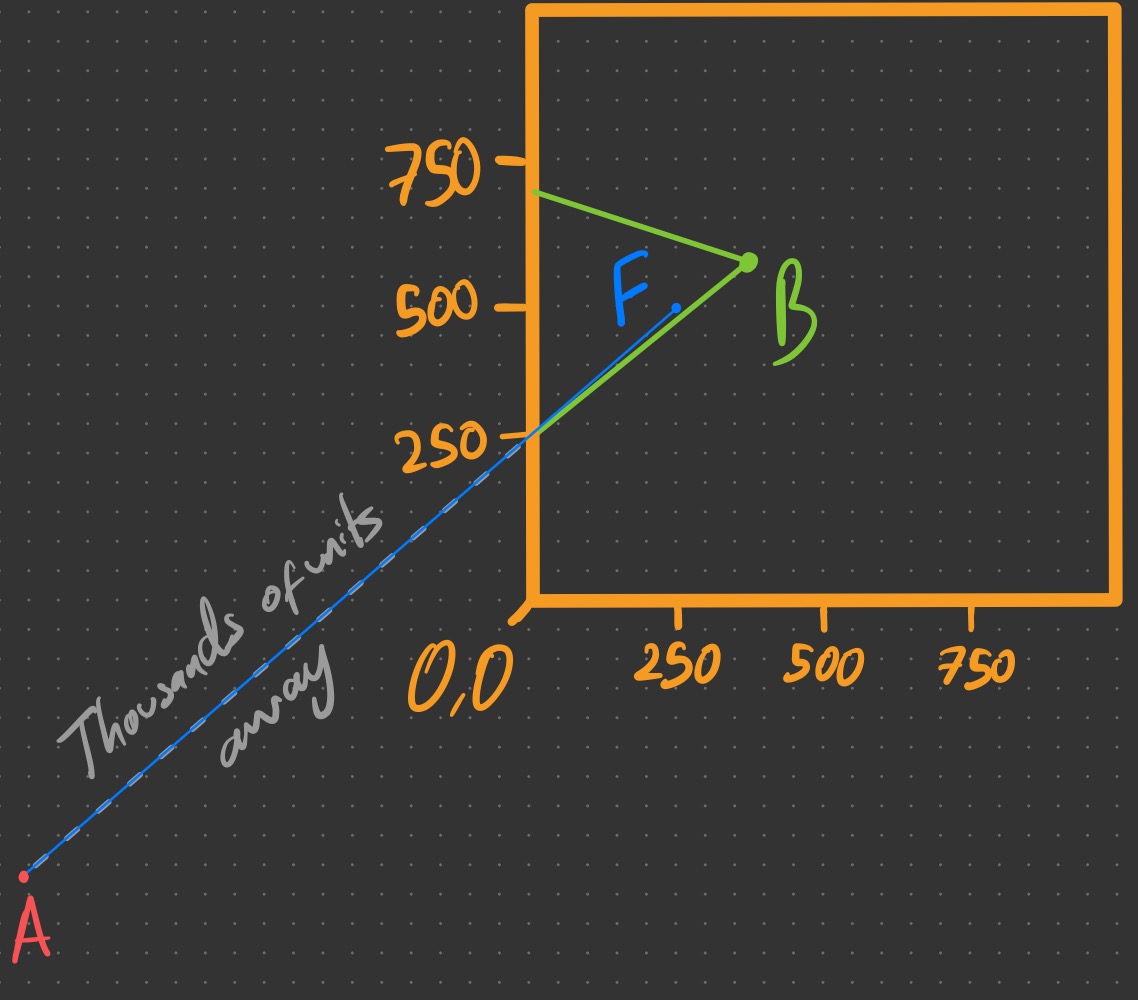
One thing you may immediately pick up from the triangle debugger data in Figure 8 & the sketch in Figure 9 is that the point $A$ is absurdly far from the triangle, about 21 viewports horizontally, since its screen-space coordinate is $A = -20990.15$.
To find the distance $d$ from $F$ to $AB$, we need to find $\proj{AF}{AB}$ (i.e., the projection of $AF$ onto $AB$) and use the Pythagoras theorem.
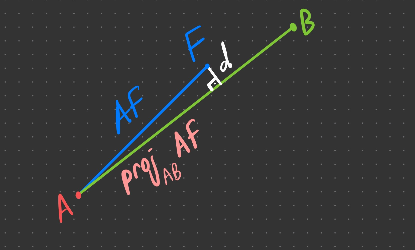
If we use $AF$ as the hypotenuse (as in Figure 10) to get the minimum distance from fragment $F$ to the edge $AB$, we run into floating-point limits. At this scale, $AF$ and $\proj{AF}{AB}$ are both about $≈ 25.000$ yet differ by only $≈ 1.5×10⁻³$.
The naive formula $d = \sqrt{AF^2 - (\proj{AF}{AB})^2}$ exhibits catastrophic cancellation. Worse, in 32-bit float, the spacing of representable numbers near $25.000$ is one ulp = $2^{14-23}=1/512\approx 0.001953125$, which is larger than $| AF^2 - (\proj{AF}{AB})^2|$.
After rounding, $AF$ and $\proj{AF}{AB}$ can become equal, making $AF^2-\proj{AF}{AB}^2$ evaluate to exactly zero for some fragments, while a 1-pixel move flips the rounding and yields a finite $d$ for neighbors. This is the 1-pixel on/off speckle we see in Figures 6 & 7.
Equivalently, even the stable rewrite $d = \sqrt{(AF-\proj{AF}{AB})(AF+\proj{AF}{AB})}$ still quantizes the first factor in float to multiples of one ulp, so the distance changes in coarse steps, unless we reduce the magnitudes of these vectors somehow.
“Half” Measure
As mentioned earlier, the proper fix for these numerical instability issues is to simply reduce the lengths of the lines we work with. Remember, we only need a direction and a point on the line to define it mathematically. So for Figure 10, we don’t necessarily need to use $A$ which is absurdly far away from the viewport; we can use any point we want, as long as it lies on the line defined by $A$ & $B$.
A quick way to test this is to use the midpoint of $A$ and $B$ whenever either vertex falls outside the view frustum.
As Figure 11 shows, the theory works in practice as well, at least for this instance (i.e., this specific camera transform). Of course, this is only a half measure; it’s easy to imagine scenarios where this crude attempt at a fix fails.
Sure enough, after a minute of moving the camera around, I found an angle where the midpoint method breaks down. It produces a slightly better result visually, but it is still not the full solution we need, though it was never meant to be. The goal here was to quickly test the idea of bringing the offscreen vertex closer by using an in-view point along the original line, in which it succeeded, as we saw this approach has merit.
The question is, why did it fail?
Let’s look at some numbers.

The triangle debugger indicates that $A$ is nearly 26 viewports away horizontally, while $B$ is only ~1.5 viewports away, in the opposite direction. This means their midpoint is still 10+ viewports away, in the direction of $A$, which is closer than $A$ but still absurdly far away. This explains why the midpoint fix works for some of the pixels but not all of them.
Full Measure
You can probably guess where this is heading: Clipping.
If we could clip the offscreen vertices to the edges of the viewport, all those pesky precision issues would simply vanish.
To that end, I implemented the Liang-Barsky line clipping algorithm in the fragment shader. After clipping to viewport borders, the midpoint of the clipped line is used as the new $AF$ and/or $BF$ vectors, as well as the $XF$ vector for the cases where the line $AB$ is visible.
Everything finally works. No glitches, no surprises, just clean wireframes.
With this, the implementation is solid. I haven’t been able to break it yet.
Below you can find the shader code. The geometry shader is identical to the paper’s, so it is omitted.
The fragment shader code contains all three methods discussed so far:
- The original method from the paper.
- Half measure: The naive midpoint method.
- Full measure: Clipping.
in VS_To_FS
{
    noperspective vec4 edge_info_A;
    noperspective vec4 edge_info_B;
    noperspective vec4 edge_info_AB;
    flat uint case_id;
} fs_in;

out vec4 out_color;

/* Liang-Barsky algorithm.
 * Returns t-enter and t-exit values calculated. */
vec2 ClipLineAgainstViewport( const vec2 p1, const vec2 p2, bool is_infinite_line )
{
    /* Edges are mapped to indices as:
     * 0: Left
     * 1: Right
     * 2: Bottom
     * 3: Top */

    const float infinity = 1.0 / 0.0;

    float t_enter = is_infinite_line ? -infinity : 0;
    float t_exit  = is_infinite_line ? +infinity : 1;
    const float p_values[ 4 ] = { p1.x - p2.x, p2.x - p1.x, p1.y - p2.y, p2.y - p1.y };
    /* x_min and y_min are always 0 since the viewport is created at 0,0 in the first place. */
    const float q_values[ 4 ] = { p1.x, _INTRINSIC_VIEWPORT_SIZE.x - p1.x, p1.y, _INTRINSIC_VIEWPORT_SIZE.y - p1.y };

    for( int i = 0; i < 4; i++ )
    {
#define pk p_values[ i ]
#define qk q_values[ i ]

        if( abs( pk ) < 1e-8 )
        {
            if( qk < 0 )
                /* Line is completely outside the viewport. Discard => return point at infinity to signal this, without breaking the math at client site. */
                return vec2( infinity, infinity );

            continue; // Avoid possible divide by zero and also qk > 0 means the line is parallel to this edge anyway.
        }

        const float t = qk / pk;

        if( pk < 0 )
            t_enter = max( t_enter, t );
        else if( pk > 0 )
            t_exit = min( t_exit, t );
    }

    if( t_enter > t_exit )
        /* Line is completely outside the viewport. Discard => return point at infinity to signal this, without breaking the math at client site. */
        return vec2( infinity, infinity );

    return vec2( t_enter, t_exit );
}

vec2 MidpointOfClippedLine( const vec2 p1, const vec2 p2, bool is_infinite_line )
{
    vec2 t_values = ClipLineAgainstViewport( p1, p2, is_infinite_line );

    vec2 entry_point = p1 + t_values[ 0 ] * ( p2 - p1 );
    vec2  exit_point = p1 + t_values[ 1 ] * ( p2 - p1 );

    return 0.5 * ( entry_point + exit_point );
}

void main()
{
    out_color.rgb = uniform_color.rgb;

    float min_distance_to_edge;

    if( fs_in.case_id == 0 )
    {
        /* The standard case: Just use the minimum of the distance-to-edge values already calculated in the geometry shader, interpolated and ready to go. */

        min_distance_to_edge = min( min( fs_in.edge_info_A.x, fs_in.edge_info_A.y ), fs_in.edge_info_A.z );

        out_color.a = 1.0;
    }
    else
    {
        /* Tricky case(s): Calculate fragment distances to the edges and use the minimum to determine wireframe status.
         * A, B and C are the vertices 1, 2 and 3 respectively.
         *
         * For case ids 3, 5 & 6, there are 2 points outside the viewport and 1 point inside.
         * This means that the edge of the triangle connected by these invisible points can be omitted completely,
         * As no wireframe will need to be rendered for a completely invisible line.
         *
         * Thus, code below computes the distance-to-edge values for the always (at least partly) visible 2 edges of the triangle.
         *
         * Refer to the figure 3 in NVIDIA's white paper "Solid Wireframe" (February 2007 WP-03014-001_v01) for further clarification. */

         /* Unpack edge info. calculated in geometry shader: */
        vec2 A_dir = fs_in.edge_info_A.zw;
        vec2 B_dir = fs_in.edge_info_B.zw;

#define IS_IN_VIEWPORT( p ) p.x >= 0 && p.x <= _INTRINSIC_VIEWPORT_SIZE.x && p.y >= 0 && p.y <= _INTRINSIC_VIEWPORT_SIZE.y

#ifdef GLITCH_FIX_MIDPOINT
        vec2 AF = IS_IN_VIEWPORT( fs_in.edge_info_A )
            ? gl_FragCoord.xy - fs_in.edge_info_A.xy
            : gl_FragCoord.xy - ( fs_in.edge_info_A.xy + fs_in.edge_info_B.xy ) * 0.5;
        vec2 BF = IS_IN_VIEWPORT( fs_in.edge_info_B )
            ? gl_FragCoord.xy - fs_in.edge_info_B.xy
            : gl_FragCoord.xy - ( fs_in.edge_info_A.xy + fs_in.edge_info_B.xy ) * 0.5;
#elif defined( GLITCH_FIX_CLIP )
        vec2 AF = IS_IN_VIEWPORT( fs_in.edge_info_A )
            ? gl_FragCoord.xy - fs_in.edge_info_A.xy
            : gl_FragCoord.xy - MidpointOfClippedLine( fs_in.edge_info_A.xy, fs_in.edge_info_A.xy + A_dir, true );
        vec2 BF = IS_IN_VIEWPORT( fs_in.edge_info_B )
            ? gl_FragCoord.xy - fs_in.edge_info_B.xy
            : gl_FragCoord.xy - MidpointOfClippedLine( fs_in.edge_info_B.xy, fs_in.edge_info_B.xy + B_dir, true );
#else // Do nothing, i.e., the method from the paper.
        vec2 AF = gl_FragCoord.xy - fs_in.edge_info_A.xy; // Vector from A to F (fragment pos.).
        vec2 BF = gl_FragCoord.xy - fs_in.edge_info_B.xy; // Vector from B to F (fragment pos.).
#endif

        /* Use pythagorean theorem to calculate the missing piece that is the minimum distance of the point F (fragment pos.) to the line(s).
         * Hypothenuse(s) are the distances from F to A and B respectively.
         * Known edges are the projections of F onto A_dir and B_dir respectively: */
        float projection_f_onto_A_dir       = dot( A_dir, AF ); // Hypothenuse.
        float projection_f_onto_B_dir       = dot( B_dir, BF ); // Hypothenuse.
        float squared_distance_to_A_A_prime = abs( dot( AF, AF ) - projection_f_onto_A_dir * projection_f_onto_A_dir );
        float squared_distance_to_B_B_prime = abs( dot( BF, BF ) - projection_f_onto_B_dir * projection_f_onto_B_dir );

        float min_squared_distance_to_edge = min( squared_distance_to_A_A_prime, squared_distance_to_B_B_prime );

        /* For cases where 2 points are in-view and 1 points is outside, there is an additional third edge we need to consider:
         * The completely visible edge AB: */
        if( fs_in.case_id == 1 || fs_in.case_id == 2 || fs_in.case_id == 4 )
        {
            vec2 AB_dir = normalize( fs_in.edge_info_B.xy - fs_in.edge_info_A.xy );

#ifdef GLITCH_FIX_MIDPOINT
            vec2 XF = fs_in.edge_info_A.x >= 0 && fs_in.edge_info_A.x <= _INTRINSIC_VIEWPORT_SIZE.x && fs_in.edge_info_A.y >= 0 && fs_in.edge_info_A.y <= _INTRINSIC_VIEWPORT_SIZE.y
                ? AF
                : fs_in.edge_info_B.x >= 0 && fs_in.edge_info_B.x <= _INTRINSIC_VIEWPORT_SIZE.x && fs_in.edge_info_B.y >= 0 && fs_in.edge_info_B.y <= _INTRINSIC_VIEWPORT_SIZE.y
                    ? BF
                    : gl_FragCoord.xy - 0.5 * ( fs_in.edge_info_A.xy + fs_in.edge_info_B.xy );
#elif defined( GLITCH_FIX_CLIP )
            vec2 XF = fs_in.edge_info_A.x >= 0 && fs_in.edge_info_A.x <= _INTRINSIC_VIEWPORT_SIZE.x && fs_in.edge_info_A.y >= 0 && fs_in.edge_info_A.y <= _INTRINSIC_VIEWPORT_SIZE.y
                ? AF
                : fs_in.edge_info_B.x >= 0 && fs_in.edge_info_B.x <= _INTRINSIC_VIEWPORT_SIZE.x && fs_in.edge_info_B.y >= 0 && fs_in.edge_info_B.y <= _INTRINSIC_VIEWPORT_SIZE.y
                    ? BF
                    : gl_FragCoord.xy - MidpointOfClippedLine( fs_in.edge_info_A.xy, fs_in.edge_info_B.xy, false );
#else // Do nothing, i.e., the method from the paper.
            vec2 XF = AF;
#endif

            float projection_f_onto_AB_dir = dot( AB_dir, XF ); // Hypothenuse.

            float squared_distance_to_AB = abs( dot( XF, XF ) - projection_f_onto_AB_dir * projection_f_onto_AB_dir );
            min_squared_distance_to_edge = min( min_squared_distance_to_edge, squared_distance_to_AB );
        }

        min_distance_to_edge = sqrt( min_squared_distance_to_edge );
    }

    // Cull fragments too far from the edge:
    if( min_distance_to_edge > uniform_line_thickness + 1 )
        discard;

    // Map the computed distance to the [0,2] range on the border of the line.
    min_distance_to_edge = clamp( ( min_distance_to_edge - ( uniform_line_thickness - 1 ) ), 0, 2 );

    // Alpha is computed from the function exp2(-2(x)^2):
    float alpha = exp2( -2 * min_distance_to_edge * min_distance_to_edge );

    out_color.a = alpha;
}
Was There Ever a Problem in the First Place?
At this stage, I was contemplating my sanity as I had produced mathematical proof on why the original paper implementation was not entirely correct, and then fixed it, but I hadn’t been able to reproduce the original glitch in the demo accompanying the paper.
Then it hit me: The triangles of the hydrant model used in the demo has relatively small triangles and the camera controls are kind of janky, making the glitch difficult to reproduce. Luckily, the demo also lets you browse for another model file of your choosing, provided it is in .x format. So I went scouring for those models from the same site where I downloaded the demo and found a mountain scene (in the Texture Arrays Terrain Rendering DirectX 10 sample, which contained nice big triangles for the terrain. And sure enough, I was able to get it to glitch!
As is evident, the demo (and by extension the paper and the accompanying shader code) also has this problem.
Final Touches
One possible improvement is to move the clipping calculations from fragment shading to geometry shading as the clipping is also constant across the triangle.
While naively clipping $A$ and $B$ to the viewport in the geometry shader may fix the problems with the $\overrightarrow{AB}$ edge, it can break the other two edges in some cases, as we’re now bringing potentially faraway (even invisible) edges near the viewport, causing incorrect edges to pop into view.
The workaround is to use separate interpolants for the $\overrightarrow{AB}$ edge: namely, the midpoint of the clipped $\overrightarrow{AB}$ and the $\overrightarrow{AB}_{dir}$ vectors.
Below are the relevant parts of the geometry shader:
/* Geometry shader code above is omitted. */

if( vs_out.case_id != 0 )
{
    /* Tricky case(s): Calculate edge info.: */
    vs_out.edge_info_A.xy = screen_space_points[ TABLE_INDICES_FOR_A[ vs_out.case_id ] ];
    vs_out.edge_info_B.xy = screen_space_points[ TABLE_INDICES_FOR_B[ vs_out.case_id ] ];

    vs_out.edge_info_A.zw = normalize( screen_space_points[ TABLE_INDICES_FOR_A_DIR[ vs_out.case_id ] ] - vs_out.edge_info_A.xy  );
    vs_out.edge_info_B.zw = normalize( screen_space_points[ TABLE_INDICES_FOR_B_DIR[ vs_out.case_id ] ] - vs_out.edge_info_B.xy  );

    /* Before clipping A and B, calculate clipping for the AB edge, as it relies on unclipped A & B data. */
    if( vs_out.case_id == 1 || vs_out.case_id == 2 || vs_out.case_id == 4 )
    {
        vs_out.edge_info_AB.zw = normalize( vs_out.edge_info_B.xy - vs_out.edge_info_A.xy );

        vs_out.edge_info_AB.xy = vs_out.edge_info_A.x >= 0 && vs_out.edge_info_A.x <= _INTRINSIC_VIEWPORT_SIZE.x && vs_out.edge_info_A.y >= 0 && vs_out.edge_info_A.y <= _INTRINSIC_VIEWPORT_SIZE.y
            ? vs_out.edge_info_A.xy
            : vs_out.edge_info_B.x >= 0 && vs_out.edge_info_B.x <= _INTRINSIC_VIEWPORT_SIZE.x && vs_out.edge_info_B.y >= 0 && vs_out.edge_info_B.y <= _INTRINSIC_VIEWPORT_SIZE.y
                ? vs_out.edge_info_B.xy
                : MidpointOfClippedLine( vs_out.edge_info_A.xy, vs_out.edge_info_B.xy, false );
    }

    /* Clip A and B edges: */
    if( vs_out.edge_info_A.x < 0 || vs_out.edge_info_A.x > _INTRINSIC_VIEWPORT_SIZE.x || vs_out.edge_info_A.y < 0 || vs_out.edge_info_A.y > _INTRINSIC_VIEWPORT_SIZE.y )
        vs_out.edge_info_A.xy = MidpointOfClippedLine( vs_out.edge_info_A.xy, vs_out.edge_info_A.xy + vs_out.edge_info_A.zw, true );
    if( vs_out.edge_info_B.x < 0 || vs_out.edge_info_B.x > _INTRINSIC_VIEWPORT_SIZE.x || vs_out.edge_info_B.y < 0 || vs_out.edge_info_B.y > _INTRINSIC_VIEWPORT_SIZE.y )
        vs_out.edge_info_B.xy = MidpointOfClippedLine( vs_out.edge_info_B.xy, vs_out.edge_info_B.xy + vs_out.edge_info_B.zw, true );

    /* Emit vertices normally: */
    gl_Position = gl_in[ 0 ].gl_Position;
    EmitVertex();

    gl_Position = gl_in[ 1 ].gl_Position;
    EmitVertex();

    gl_Position = gl_in[ 2 ].gl_Position;
    EmitVertex();

    EndPrimitive();
}
/* Geometry shader code below is omitted. */
Fragment shader code is simply reverted back to the paper’s code mostly, except for this block, which uses the $\overrightarrow{AB}$ and the $\overrightarrow{AB}_{dir}$ vectors calculated in the geometry shader, residing in the interpolant fs_in.edge_info_AB:
/* Fragment shader code above is omitted. */

if( fs_in.case_id == 1 || fs_in.case_id == 2 || fs_in.case_id == 4 )
{
    vec2 XF = gl_FragCoord.xy - fs_in.edge_info_AB.xy; // Vector from AB to F (fragment pos.).

    float projection_f_onto_AB_dir = dot( fs_in.edge_info_AB.zw, XF ); // Hypothenuse.

    float squared_distance_to_AB = abs( dot( XF, XF ) - projection_f_onto_AB_dir * projection_f_onto_AB_dir );
    min_squared_distance_to_edge = min( min_squared_distance_to_edge, squared_distance_to_AB );
}

/* Fragment shader code below is omitted. */
Conclusion
The wireframe saga finally comes to a close. This one took a lot out of me: math, debugging, rasterization fundamentals, and whatnot. If you made it to the end, thanks for sticking around! Hopefully this series saves you some pain or at least gives you a few “ah-ha” moments I wish I had sooner.
Now to break something else. Onward!
Image credits: Figures reproduced from NVIDIA’s Solid Wireframe whitepaper (2007) are the copyright of NVIDIA Corporation and are used here under fair use for the purposes of commentary and analysis.
Graphics Programming OpenGL Kakadu Wireframe Rendering Optimizations GPU Precision Liang-Barsky Clipping